
Example n° 3: Serving a large number of Cartographic Black/White GeoTiff with Palette
In this example there is a group of Cartographic Black/White images from “CARTA TECNICA DELLA REGIONE TOSCANA”. The purpose of this example is to describe how the GDAL commands may be used for merging the input files provided.
Note
On a Windows machine you can set-up a shell with all GDAL Utilities, running directly the file OSGeo4W.bat under the %TRAINING_ROOT% folder.
Note
Data have the same pixel resolution and same Coordinate Reference System EPSG:25832. Also each pixel is stored into a single bit.
- Navigate to the workshop directory
$TRAINING_ROOT/data/user_data/gdal_processing_data(on Windows%TRAINING_ROOT%\data\user_data\gdal_processing_data) and find the CTR_data directory. - Navigate inside the CTR_data directory with the GDAL shell.
Note
The following operations must be executed from the shell inside the selected directory.
Calling the gdalinfo command on an image for retrieving the associated information:
gdalinfo 20E27_1994.TIF
And the result is:
Driver: GTiff/GeoTIFF
Files: 20E27_1994.TIF
           20E27_1994.TFW
Size is 16050, 14050
Coordinate System is `'
GeoTransform =
  600769.026848671, 0.1, 7.3789937e-007
  4863785.940434861, -8.172141e-008, -0.1
Metadata:
  TIFFTAG_RESOLUTIONUNIT=2 (pixels/inch)
  TIFFTAG_SOFTWARE=IrfanView
  TIFFTAG_XRESOLUTION=72
  TIFFTAG_YRESOLUTION=72
Image Structure Metadata:
  COMPRESSION=PACKBITS
  INTERLEAVE=BAND
  MINISWHITE=YES
Corner Coordinates:
Upper Left  (  600769.027, 4863785.940)
Lower Left  (  600769.037, 4862380.940)
Upper Right (  602374.027, 4863785.939)
Lower Right (  602374.037, 4862380.939)
Center      (  601571.532, 4863083.440)
Band 1 Block=16050x4 Type=Byte, ColorInterp=Palette
  Image Structure Metadata:
        NBITS=1
  Color Table (RGB with 2 entries)
        0: 255,255,255,255
        1: 0,0,0,255
From gdalinfo it is possible to note:
- No CRS definition. An image without CRS cannot be displayed on GeoServer.
- Color Interpretation as palette.
- A GeoTransformation matrix is associated.
- Tiles Striped (16050x4).
- Packbits Compression.
Executing the following commands on the tiff images:
gdalwarp -t_srs EPSG:25832 -of vrt $f ${f:0:10}_temp.vrt

gdal_translate -expand gray -of vrt ${f:0:10}_temp.vrt ${f:0:10}.vrt
The first operation sets the CRS to each image and creates a VRT file, for reducing space occupation. Also the use of gdalwarp internally performs the GeoTransformation associated to the image.
The second operation is used for changing the color interpretation from palette to gray. This operation is done because in the final steps other grey levels will be added with the interpolation. The expansion to the gray color interpretation leads to an expansion of the pixel dimension from 1 to 8 bits.
Note
The expand gray option does not create a multi banded image but only a single banded one.
Note
If the user wants to keep the palette, then can go directly to the Optional elaboration without expanding the Palette paragraph.
These operations must be executed inside a script:
Linux:
#!/bin/bash FILES="*.TIF" echo start for f in $FILES do echo $f gdalwarp -t_srs EPSG:25832 -of vrt $f ${f:0:10}_temp.vrt gdal_translate -expand gray -of vrt ${f:0:10}_temp.vrt ${f:0:10}.vrt done echo stopWindows:
for /R %%f in (*.tif) do (
        gdalwarp -t_srs EPSG:25832 -of vrt %%~f %%~f_temp.vrt
        gdal_translate -expand gray -of vrt %%~f_temp.vrt %%~f.vrt
)
Listing of all the VRT files into a single text list with the following command:
ls *TIF.vrt > list.txt (Linux)

or

dir /b *TIF.vrt > list.txt (Windows)
Merging of all the input files with the gdalbuildvrt command:
gdalbuildvrt -srcnodata 255 -vrtnodata 255 -input_file_list list.txt merged_vrt.vrt
Parameters used:
- -srcnodata 255 -vrtnodata 255 : definition of the No Data associated with the file.
- -input_file_list list.txt : definition of input files to elaborate.
The gdalinfo output on the merged image is:
Driver: VRT/Virtual Raster
Files: merged_vrt.vrt
           20E27_1994.TIF.vrt

           ~

           20E60_1995.TIF.vrt
Size is 50052, 62047
Coordinate System is:
PROJCS["ETRS89 / UTM zone 32N",
        GEOGCS["ETRS89",
                DATUM["European_Terrestrial_Reference_System_1989",
                        SPHEROID["GRS 1980",6378137,298.257222101,
                                AUTHORITY["EPSG","7019"]],
                        TOWGS84[0,0,0,0,0,0,0],
                        AUTHORITY["EPSG","6258"]],
                PRIMEM["Greenwich",0,
                        AUTHORITY["EPSG","8901"]],
                UNIT["degree",0.0174532925199433,
                        AUTHORITY["EPSG","9122"]],
                AUTHORITY["EPSG","4258"]],
        PROJECTION["Transverse_Mercator"],
        PARAMETER["latitude_of_origin",0],
        PARAMETER["central_meridian",9],
        PARAMETER["scale_factor",0.9996],
        PARAMETER["false_easting",500000],
        PARAMETER["false_northing",0],
        UNIT["metre",1,
                AUTHORITY["EPSG","9001"]],
        AXIS["Easting",EAST],
        AXIS["Northing",NORTH],
        AUTHORITY["EPSG","25832"]]
Origin = (600768.734234663190000,4863785.940434861000000)
Pixel Size = (0.100000372821407,-0.100000372821407)
Corner Coordinates:
Upper Left  (  600768.734, 4863785.940) ( 10d15'18.69"E, 43d55'13.06"N)
Lower Left  (  600768.734, 4857581.217) ( 10d15'14.46"E, 43d51'51.99"N)
Upper Right (  605773.953, 4863785.940) ( 10d19' 3.07"E, 43d55'10.54"N)
Lower Right (  605773.953, 4857581.217) ( 10d18'58.64"E, 43d51'49.47"N)
Center      (  603271.344, 4860683.579) ( 10d17' 8.72"E, 43d53'31.28"N)
Band 1 Block=128x128 Type=Byte, ColorInterp=Gray
  NoData Value=255
Transforming from VRT to GeoTiff with gdal_translate:
gdal_translate -a_nodata none -co "BLOCKXSIZE=512" -co "BLOCKYSIZE=512" -co "TILED=YES" -co "BIGTIFF=YES" -co "COMPRESS=DEFLATE" merged_vrt.vrt merged_tif.tif
The various input parameters are:
-a_nodata none : avoid setting 255 as No Data for a better image optimization.
-co “BLOCKXSIZE=512” -co “BLOCKYSIZE=512” -co “TILED=YES” : definition of the tile dimensions.
-co “BIGTIFF=YES” -co “COMPRESS=DEFLATE” : definition of the compression method.
Note
BIGTIFF=YES must be set for big images because when compression is used, by default gdal_translate is not able to check if the final image is a BigTiff or not.
From gdalinfo:
Driver: GTiff/GeoTIFF
Files: merged_tif.tif
Size is 50052, 62047
Coordinate System is:
PROJCS["ETRS89 / UTM zone 32N",
        GEOGCS["ETRS89",
                DATUM["European_Terrestrial_Reference_System_1989",
                        SPHEROID["GRS 1980",6378137,298.2572221010002,
                                AUTHORITY["EPSG","7019"]],
                        TOWGS84[0,0,0,0,0,0,0],
                        AUTHORITY["EPSG","6258"]],
                PRIMEM["Greenwich",0],
                UNIT["degree",0.0174532925199433],
                AUTHORITY["EPSG","4258"]],
        PROJECTION["Transverse_Mercator"],
        PARAMETER["latitude_of_origin",0],
        PARAMETER["central_meridian",9],
        PARAMETER["scale_factor",0.9996],
        PARAMETER["false_easting",500000],
        PARAMETER["false_northing",0],
        UNIT["metre",1,
                AUTHORITY["EPSG","9001"]],
        AUTHORITY["EPSG","25832"]]
Origin = (600768.734234663190000,4863785.940434861000000)
Pixel Size = (0.100000372821407,-0.100000372821407)
Metadata:
  AREA_OR_POINT=Area
Image Structure Metadata:
  COMPRESSION=DEFLATE
  INTERLEAVE=BAND
Corner Coordinates:
Upper Left  (  600768.734, 4863785.940) ( 10d15'18.69"E, 43d55'13.06"N)
Lower Left  (  600768.734, 4857581.217) ( 10d15'14.46"E, 43d51'51.99"N)
Upper Right (  605773.953, 4863785.940) ( 10d19' 3.07"E, 43d55'10.54"N)
Lower Right (  605773.953, 4857581.217) ( 10d18'58.64"E, 43d51'49.47"N)
Center      (  603271.344, 4860683.579) ( 10d17' 8.72"E, 43d53'31.28"N)
Band 1 Block=512x512 Type=Byte, ColorInterp=Gray
This image can be displayed on GeoServer but a further optimization step could bring to better performances. There could be two ways for optimizing the GeoServer performances:
- building image overviews.
- building a pyramid of the image.
(Optional) Optimization methods. Here are described two possible optimizations each of them using a different interpolation type:
Creation of the overviews associated to the merged image for having better throughput:
gdaladdo -r average merged_tif.tif 2 4 8 16 32 64 128
Overviews are reduced views of the input image used by GeoServer for displaying the image at a lower resolutions.
Parameters used:
- -r average : definition of the interpolation method.
- 2 ~ 128 : definition of the overviews level
And with gdalinfo:
Driver: GTiff/GeoTIFF
Files: merged_tif.tif
Size is 50052, 62047

~

Band 1 Block=512x512 Type=Byte, ColorInterp=Gray
  Overviews: 25026x31024, 12513x15512, 6257x7756, 3129x3878, 1565x1939, 783x970, 392x485
Then the result can be displayed in GeoServer by configuring the image as a GeoTiff (see Adding a GeoTiff section).
(Optional) Creation of a pyramid associated to the merged image and displaying the image on GeoServer with the ImagePyramid plugin (see Advanced Mosaic and Pyramid configuration section).
For building a pyramid the gdalwarp command must be called several times. The operation to execute on the first image is:
gdalwarp -r cubic -multi -tr 0.200000745642814 -0.200000745642814 -co BLOCKXSIZE=512 -co BLOCKYSIZE=512 -co TILED=YES -co COMPRESS=DEFLATE merged_tif.tif merged_tif_2.tif
The parameters are:
- -r cubic : definition of the interpolation method (average interpolation can be used only with GDAL 1.10).
- -multi : forcing to use multithreading.
- -tr 0,200000745642814 -0,200000745642814 : definition of the image resolution.
From gdalinfo on the result image:
Driver: GTiff/GeoTIFF
Files: merged_tif_2.tif
Size is 25026, 31024

~

Band 1 Block=512x512 Type=Byte, ColorInterp=Gray
Then the same operation, with another value for the resolution must be executed on the result image:
gdalwarp -r cubic -multi -tr 0.400001491285628 -0.400001491285628 -co BLOCKXSIZE=512 -co BLOCKYSIZE=512 -co TILED=YES -co COMPRESS=DEFLATE merged_tif_2.tif merged_tif_4.tif
These operation must be repeated until the final image has a resolution 128 times lower than that of the initial image.
Note
Each call of gdalwarp reduces by half the image resolution.
After creating the various rasters, they must be saved inside a new directory. This directory must be internally divided into sub-directories numbered from 1 to 7, each of them containing a raster of smaller dimension(going from 1 to 7) and leaving the original raster in the super-directory.
Then the user can configure the following structure with the ImagePyramid plugin.
Displaying the result on GeoServer:
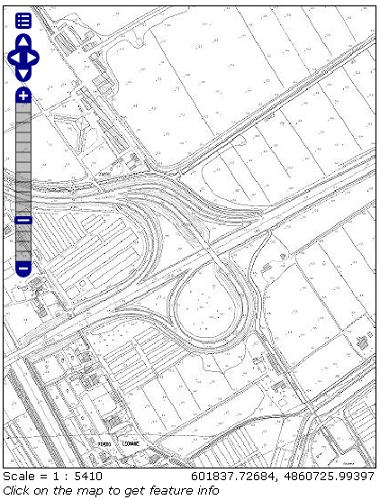
Result as a pyramid (Zoom on the image for seeing the result).
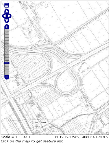
Result with overviews (Zoom on the image for seeing the result).
Optional elaboration without expanding the Palette
If the user wants to keep the palette the steps to achieve are quite similar.
Executing the following commands on the tiff images:
gdalwarp -t_srs EPSG:25832 -of vrt $f ${f:0:10}_temp.vrt

gdal_translate -of vrt ${f:0:10}_temp.vrt ${f:0:10}.vrt
These operations must be executed inside a script:
Linux:
#!/bin/bash FILES="*.TIF" echo start for f in $FILES do echo $f gdalwarp -t_srs EPSG:25832 -of vrt $f ${f:0:10}_temp.vrt gdal_translate -of vrt ${f:0:10}_temp.vrt ${f:0:10}.vrt done echo stopWindows:
for /R %%f in (*.tif) do (
        gdalwarp -t_srs EPSG:25832 -of vrt %%~f %%~f_temp.vrt
        gdal_translate -of vrt %%~f_temp.vrt %%~f.vrt
)
Listing of all the VRT files into a single text list with the following command:
ls *.vrt > list.txt (Linux)

or

dir /b *.vrt > list.txt (Windows)
Warning
Delete the _temp.vrt files from the list because they overlap with the final vrt files created.
Merging of all the input files with the gdalbuildvrt command:
gdalbuildvrt -srcnodata 0 -vrtnodata 0 -input_file_list list.txt merged_vrt.vrt
Parameters used:
- -srcnodata 0 -vrtnodata 0 : definition of the No Data associated with the file.
- -input_file_list list.txt : definition of input files to elaborate.
The gdalinfo output on the merged image is:
Driver: VRT/Virtual Raster
Files: merged_vrt.vrt
20E27_1994.TIF.vrt

~

20E60_1995.TIF.vrt
Size is 50052, 62047
Coordinate System is:
PROJCS["ETRS89 / UTM zone 32N",
        GEOGCS["ETRS89",
                DATUM["European_Terrestrial_Reference_System_1989",
                        SPHEROID["GRS 1980",6378137,298.257222101,
                                AUTHORITY["EPSG","7019"]],
                        TOWGS84[0,0,0,0,0,0,0],
                        AUTHORITY["EPSG","6258"]],
                PRIMEM["Greenwich",0,
                        AUTHORITY["EPSG","8901"]],
                UNIT["degree",0.0174532925199433,
                        AUTHORITY["EPSG","9122"]],
                AUTHORITY["EPSG","4258"]],
        PROJECTION["Transverse_Mercator"],
        PARAMETER["latitude_of_origin",0],
        PARAMETER["central_meridian",9],
        PARAMETER["scale_factor",0.9996],
        PARAMETER["false_easting",500000],
        PARAMETER["false_northing",0],
        UNIT["metre",1,
                AUTHORITY["EPSG","9001"]],
        AXIS["Easting",EAST],
        AXIS["Northing",NORTH],
        AUTHORITY["EPSG","25832"]]
Origin = (600768.734234663190000,4863785.940434861000000)
Pixel Size = (0.100000372821407,-0.100000372821407)
Corner Coordinates:
Upper Left  (  600768.734, 4863785.940) ( 10d15'18.69"E, 43d55'13.06"N)
Lower Left  (  600768.734, 4857581.217) ( 10d15'14.46"E, 43d51'51.99"N)
Upper Right (  605773.953, 4863785.940) ( 10d19' 3.07"E, 43d55'10.54"N)
Lower Right (  605773.953, 4857581.217) ( 10d18'58.64"E, 43d51'49.47"N)
Center      (  603271.344, 4860683.579) ( 10d17' 8.72"E, 43d53'31.28"N)
Band 1 Block=128x128 Type=Byte, ColorInterp=Palette
  NoData Value=0
  Color Table (RGB with 2 entries)
        0: 255,255,255,255
        1: 0,0,0,255
Transforming from VRT to GeoTiff with gdal_translate:
gdal_translate -co "NBITS=1" -co "BLOCKXSIZE=512" -co "BLOCKYSIZE=512" -co "TILED=YES" -co "BIGTIFF=YES" -co "COMPRESS=DEFLATE" merged_vrt.vrt merged_tif.tif
The various input parameters are:
-co “NBITS=1” : sets the bits per pixel to 1, because the Palette contains only 0 or 1.
-co “BLOCKXSIZE=512” -co “BLOCKYSIZE=512” -co “TILED=YES” : definition of the tile dimensions.
-co “BIGTIFF=YES” -co “COMPRESS=DEFLATE” : definition of the compression method.
Note
BIGTIFF=YES must be set for big images because when compression is used, by default gdal_translate is not able to check if the final image is a BigTiff or not.
From gdalinfo:
Size is 50052, 62047
Coordinate System is:
PROJCS["ETRS89 / UTM zone 32N",
        GEOGCS["ETRS89",
                DATUM["European_Terrestrial_Reference_System_1989",
                        SPHEROID["GRS 1980",6378137,298.2572221010002,
                                AUTHORITY["EPSG","7019"]],
                        TOWGS84[0,0,0,0,0,0,0],
                        AUTHORITY["EPSG","6258"]],
                PRIMEM["Greenwich",0],
                UNIT["degree",0.0174532925199433],
                AUTHORITY["EPSG","4258"]],
        PROJECTION["Transverse_Mercator"],
        PARAMETER["latitude_of_origin",0],
        PARAMETER["central_meridian",9],
        PARAMETER["scale_factor",0.9996],
        PARAMETER["false_easting",500000],
        PARAMETER["false_northing",0],
        UNIT["metre",1,
                AUTHORITY["EPSG","9001"]],
        AUTHORITY["EPSG","25832"]]
Origin = (600768.734234663190000,4863785.940434861000000)
Pixel Size = (0.100000372821407,-0.100000372821407)
Metadata:
  AREA_OR_POINT=Area
Image Structure Metadata:
  COMPRESSION=DEFLATE
  INTERLEAVE=BAND
Corner Coordinates:
Upper Left  (  600768.734, 4863785.940) ( 10d15'18.69"E, 43d55'13.06"N)
Lower Left  (  600768.734, 4857581.217) ( 10d15'14.46"E, 43d51'51.99"N)
Upper Right (  605773.953, 4863785.940) ( 10d19' 3.07"E, 43d55'10.54"N)
Lower Right (  605773.953, 4857581.217) ( 10d18'58.64"E, 43d51'49.47"N)
Center      (  603271.344, 4860683.579) ( 10d17' 8.72"E, 43d53'31.28"N)
Band 1 Block=512x512 Type=Byte, ColorInterp=Palette
  NoData Value=0
  Image Structure Metadata:
        NBITS=1
  Color Table (RGB with 2 entries)
        0: 255,255,255,255
        1: 0,0,0,255
(Optional) Optimization methods described here are similar to that described above:
- The overview creation method is equal to that described above.
- For creating the pyramid the commands to use are the same as described above with the addition of the -co “NBITS=1” command.
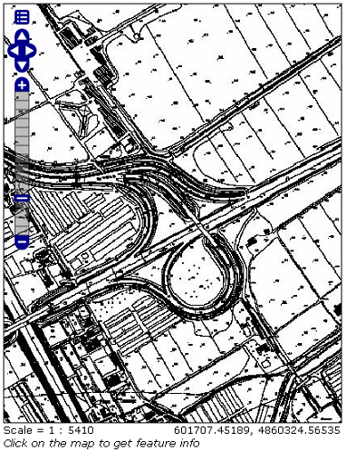
Displaying the result on GeoServer:

Result as a pyramid (Zoom on the image for seeing the result).
Result with overviews (Zoom on the image for seeing the result).